|
Cartwright Hotel, San Francisco, CA
Contractor: Empire Elevator Co., Inc.
Major alteration of 1913 Otis basement winding drum, 10
story passenger elevator.
New Hollister Whitney #54 O.D. basement machine,
counterweight, sling & platform, safeties, governors,
seismic reinforced guiderails, GAL door equip, MCE controls, cab & fixtures.
RCB Elevator Consulting, LLC and its associate structural
engineering firm performed all of
the elevator and building engineering required to make the
conversion. This included performing all field
surveys.
 Project Description
This project is a good example of a full conversion of an
ancient basement winding drum system into a modern geared
basement traction passenger elevator. Typical with
these jobs, the existing structure and costs preclude a
complete tear-out of the existing system, enlarging the
hoistway, building a new machine room, etc., which would be
required to install a new, pre-engineered elevator system.
Instead, the order is to alter the existing system to bring
it up to today's operational standards, the the extent that
that is possible.
Without giving away all of my secrets, we were able to
anchor the new basement machine into the existing building
structure without demolition beyond the removal of the
existing upper machine components. Although we married
the new machine to the old Otis machine cast steel base,
that original base accounts for none of the upthrust loads.
All of those loads are transferred to the existing structure
through a combination of new connection points.
The new overhead sheaves required were connected and
supported by a combination of the reuse of some of the
original beams in their original locations, some original
beams reused but relocated and some new steel. A new
overhead service deck was installed to enhance safety.
This winding drum installation, like so many, used a
second independent rope loop from the car to the
counterweight, which never see the drive machine. As
such, the old sash-weight-type counterweight had independent
upper and lower sections. This arrangement allows the
counterweight to be lighter, which along with other code
considerations, makes them unsuitable for reuse.
So a new counterweight was required and due to its
greater weight, the stress to the existing 8 lb/ft
guiderails far exceeded the 5% allowance. As with most
of these conversions, space constraints preclude the
installation of heavier rails. The existing guiderails
were retained in their original locations along with their
original, inadequate bracketing. Additional steel and
anchors were applied using creative engineering to reinforce
the rail stacks to meet the new loads.
In fact, all of the structural elements of the converted
systems were fully structurally calculated and designed not
only to meet the standard A17.1 code requirement but to
comply with the stress and deflection criteria of the
seismic code (A17.1-1996, Part 24).
It is critical that a job such as this that be properly
engineered. We have seen cases where the materials and
equipment are ordered and delivered to the job with
negligible thought or planning with regard to how it will
all go together. The "plan" is for the mechanic to
"engineer" the job "by the seat of his/her pants."
I've met and worked with many very good modernization
mechanics. But very, very few have the math and
engineering skills to prepare the proper calculations to
prove out support member sizes in compliance with the
deflection criteria, bolting and welding strength
sufficiency, etc. For this reason, the code requires
the review of a licensed engineer for altering members that
support the elevator system.
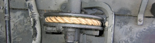
Pictures

A classic early 1900s Otis basement winding drum drive
machine. The new Hollister Whitney #54 O.D. Basement
Set geared drive machine is located in its place via an
adapter plate and with structural connections to the
building independent of the old Otis base (see drawings
below).

The old sheaves original three loop system whereby ropes
travel from the machine drum to the car, the machine O.D.
sheave to the first stage of the counterweight and a
separate, independent loop between the car and the second
stage of the counterweight. These were replaced with
new overhead sheave reusing many of the original beams, some
relocated and some new steel.

This picture shows the original screen work platform which
was replaced with steel deck. It also shows the
inadequate rail bracketing, which were reinforced to meet
the new loading per seismic standards.
Drawings & Engineering
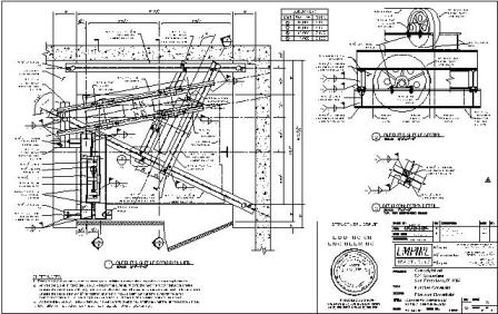
Click on the drawing above to open the full drawing set in
PDF format. To see drawings in landscape view, click
on your Adobe Reader's Rotate Counterclockwise image button.
Note drawings cannot be printed or altered. All
drawings and artwork are the property of RCB Elevator
Consulting, LLC and may not be used, copied, or in anyway
used without the owner's consent.
|